
17 February 2021
I built a dynamically assignable macro keyboard with an e-ink screen. What does that mean? Well, it is a device that pretends to be a regular keyboard, but the meaning of each button changes depending on which application you currently try to control. Let me show you in a video:

So, you now have an idea what I am talking about? Then let me explain the details in this article.
Please note that this article contains affiliate links, i.e. links that tell the target site that I sent you there and that earn me a share of their revenue in return, i.e. as an Amazon Associate I earn from qualifying purchases. In contrast to regular external links, such affiliate links are marked with a dollar sign instead of a box.
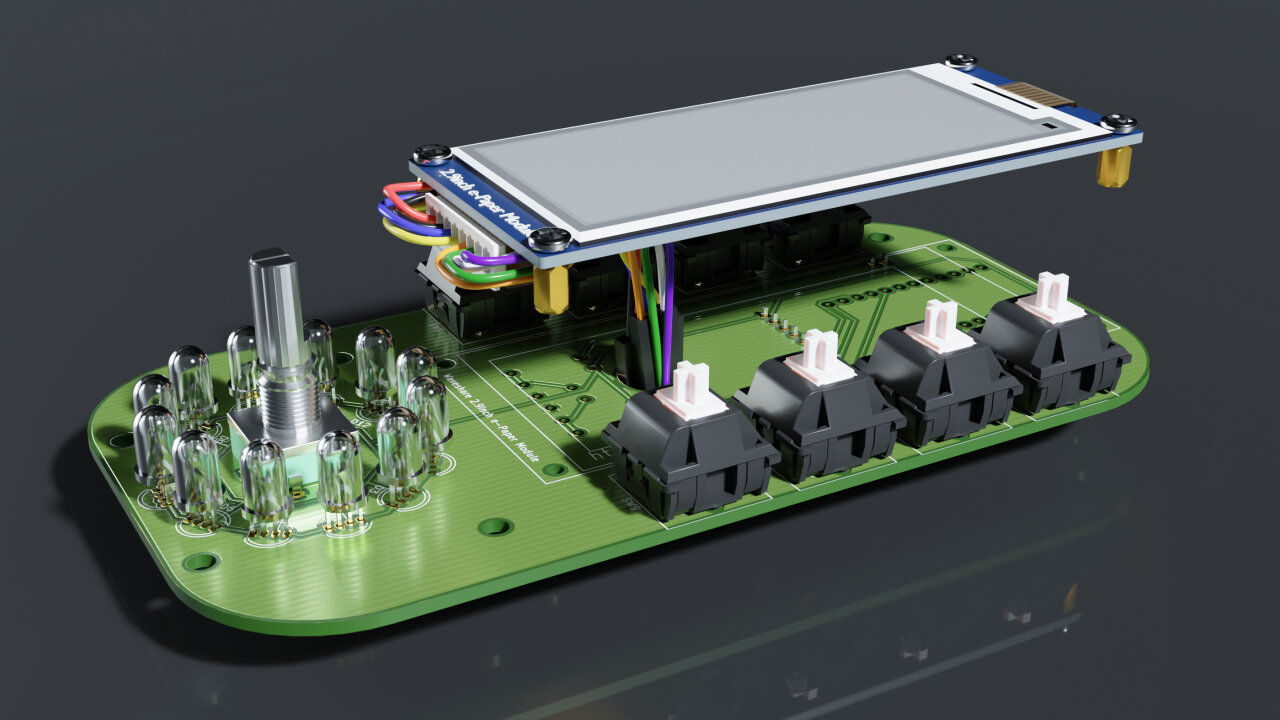
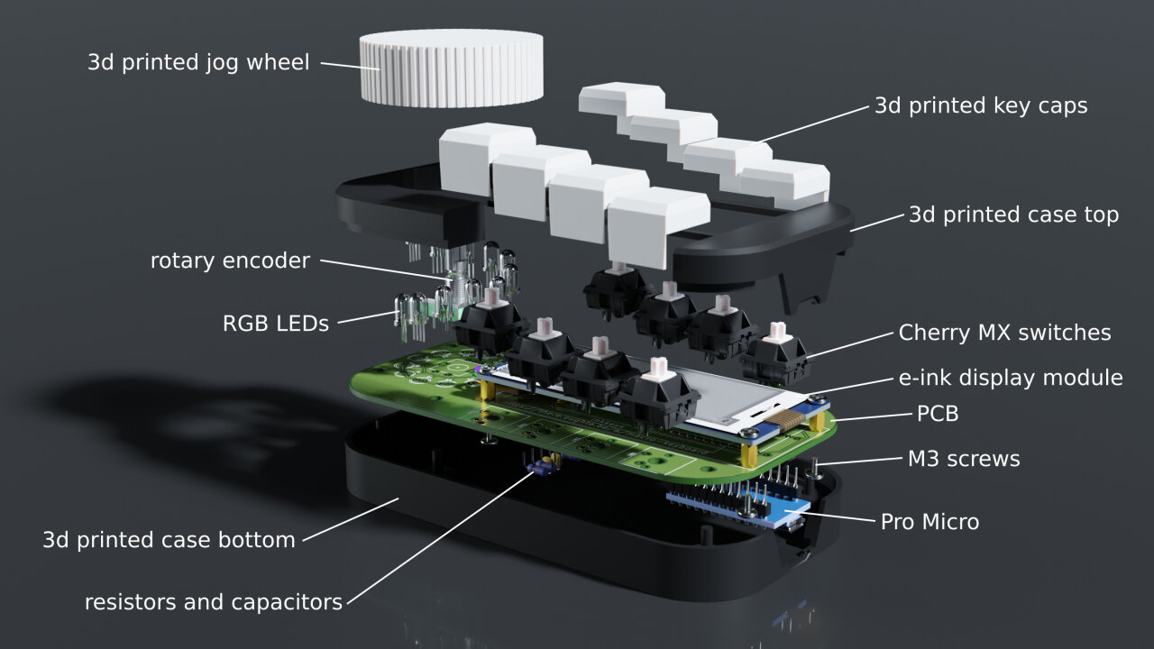
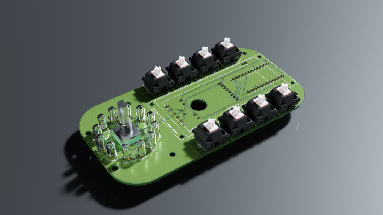
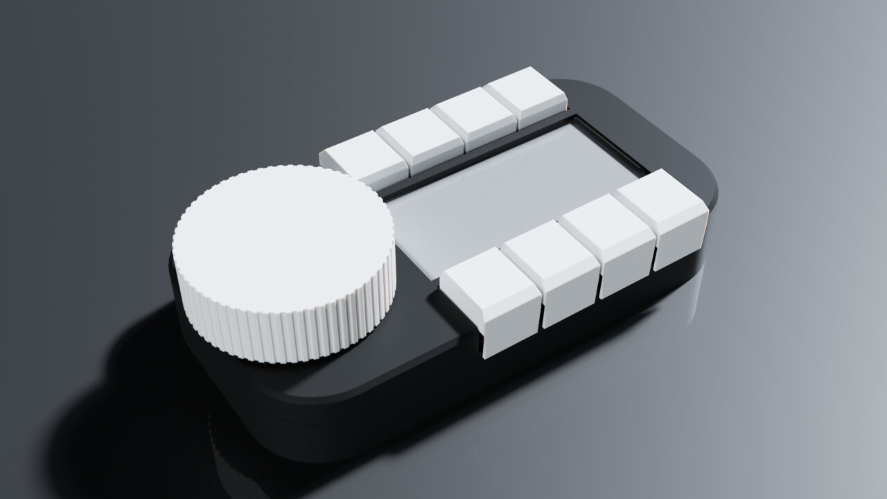
As you can see from the pictures, it is a device with eight buttons, a large dial and a display and it is plugged into a PC via USB. There it registers as a regular keyboard and sends individual key events or sequences of keypresses if I push one of the buttons. So, it is a macro keyboard - a keyboard to send macros.
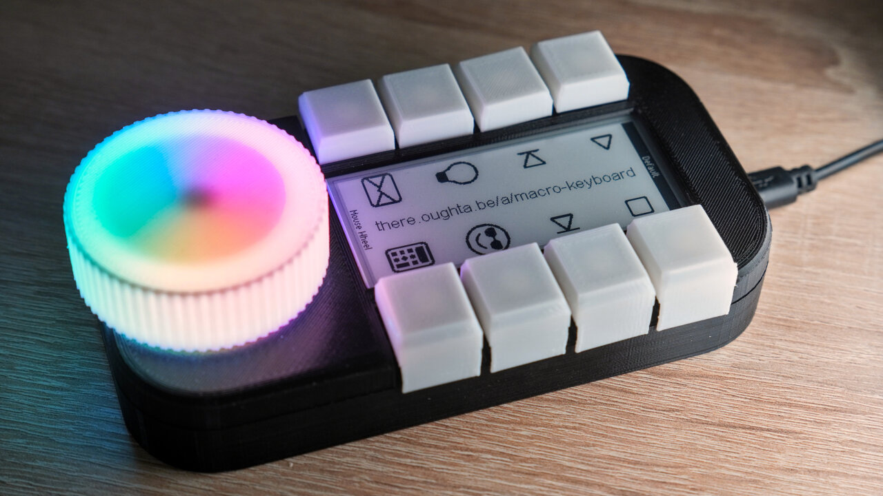
The special thing about it is that I can dynamically reassign keys and display the current key assignment on an e-ink screen. So, for example, by default the top four keys are assigned to media control keys: Play, pause and skip buttons. If I press them, the device sends the media buttons to the PC as if those buttons were pushed on a normal keyboard with multimedia keys. But if I open up Gimp1, the keys change their meaning to functions within Gimp, which I need regularly and for which I cannot remember the shortcuts: For example “cut size to the selected area”, “automatically cut the image size to the content” etc.
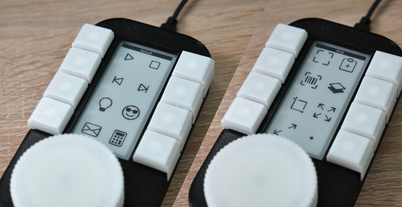
Those are actually not simple key strokes and these particular examples do not even have a direct shortcut. Instead, if I press the “cut to selection” button, the device sends a quick sequence of “Alt+B” to open the image menu, followed by “Z” to select the function from the menu2. At the same time, the device shows some icons next to the buttons to tell me, which assignment is currently active.
Keystrokes or sequences cannot only be assigned to those eight buttons, but also to the big knob at the bottom. This is designed as a so-called jog wheel, commonly used in video editing to precisely move to a specific frame while at the same time allowing to quickly skip larger periods with the same control element3. In Gimp, it controls the tool size (brush size, pen size, eraser size, you get the idea…) or the tool opacity (brush opacity, alright, you know). How can it control both? Well, it doubles as another button. You can press the wheel and trigger a ninth4 button, which can also be associated with keypresses. However, in this case it is not set to send a keystroke, but instead triggers a script to switch the function of turning the wheel.
I actually use this a lot to control additional things with Python or to switch functions of the buttons. The default layout has a button that triggers an MQTT message (in a Python script) to switch a lamp in my office. Of course the script also listens for state changes of the lamp, so the icon on the e-ink screen changes accordingly5.
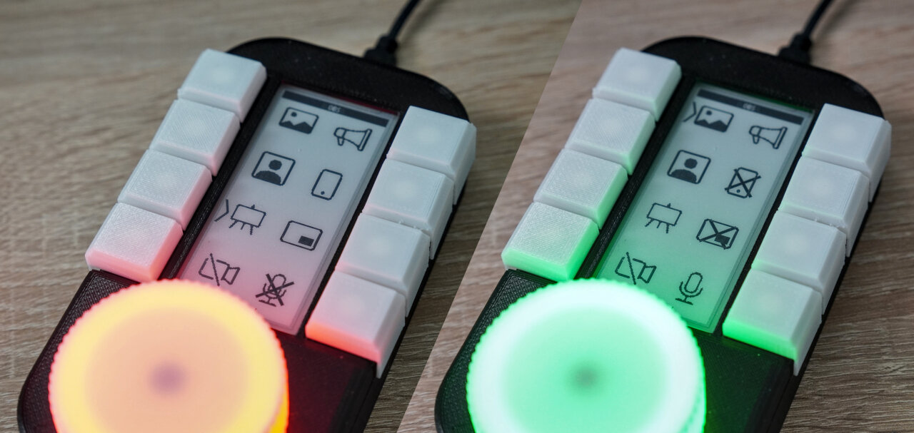
Similarly, I use Python to control OBS6 via its websockets plugin. If OBS is running, the left set of buttons allows me to switch scenes (a broader moderation view, a close-up shot, sharing slides with the close-up as picture-in-picture frame and an empty “video mute” scene) and the right set of buttons controls elements (microphone mute, overlay screen of my phone, picture-in-picture of the slide scene etc.). This is actually the main reason why I designed this macro keyboard in the first place: I needed a bunch of shortcuts for OBS and could not find a set that was easy to find while talking into a camera and that at the same time did not interfere with common shortcuts. In this case, though, I am not even sending keypresses but activating scenes and changing visibility of components via the websockets plugin from Python. The advantage is that this also allows me to retrieve the current state from OBS and visualize it on the e-ink screen accordingly.
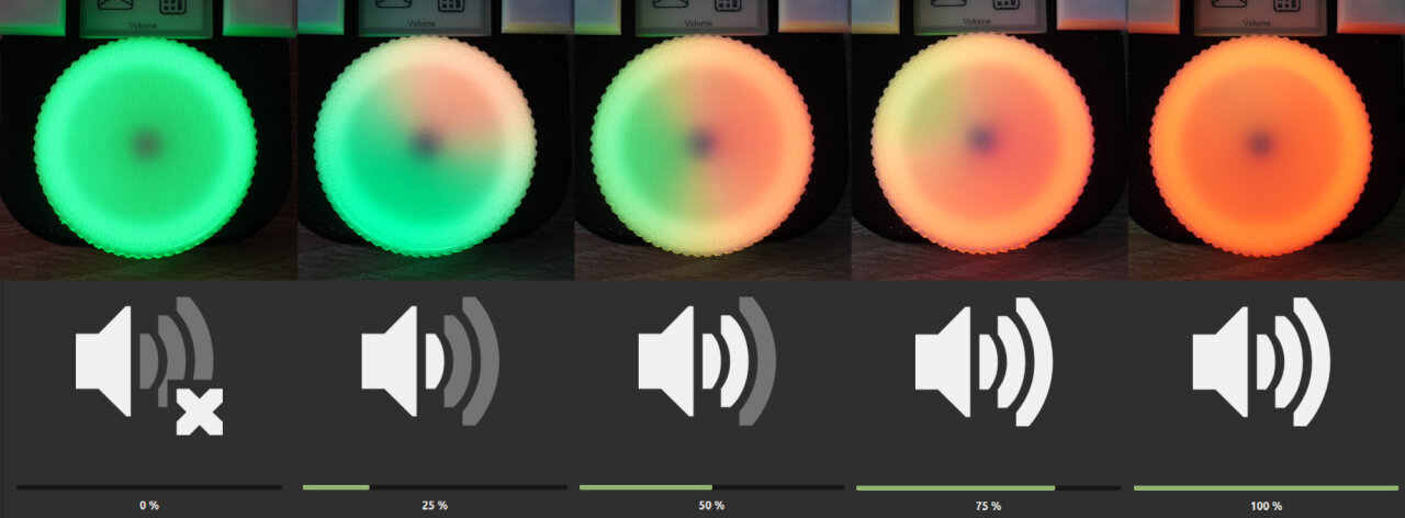
In its default settings, the function of the wheel can be switched between a mouse wheel, simple arrow keys left/right and a volume control. In case of the volume control the rotation actually does two things: It sends the volume up/down keys like volume controls on a keyboard, but it also triggers a Python script that checks the system volume and visualizes it with the LEDs below the wheel.
Oh, I did not yet mention those? Well, there are 12 individually addressable RGB LEDs below the jog dial as another means to visualize its function, to notify of some events (a blue pulse means that the CO2 sensor in my office indicates that it is time to vent) or to show a status (like red or green if the microphone is muted or not in OBS during a Zoom call)7. In case of the volume control, a number of LEDs changes from green to red depending on the volume level reported back by the system.
I think at this point you have a good idea of what this device can do. Actually, there are so many more possible applications and certainly a lot of things I have not even thought of. I also imagine that gamers can do a lot with these buttons - at least in games where moving your hand to a second device is not slowing you down too much. Let me tell you how this versatility is achieved, so you can get your own imagination going.
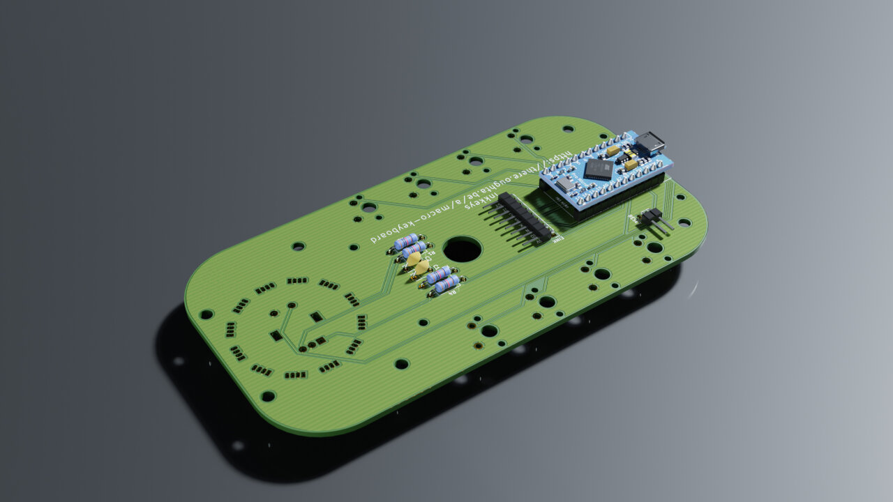
At the heart of the macro keyboard is a Pro Micro, an Arduino-compatible microcontroller, which I have chosen for one simple reason: Its ATmega32U4 supports up to six USB endpoints8. If you plug it into your PC, the PC will not only see a regular USB keyboard, but also a USB mouse, a USB “consumer keyboard” (extension for multimedia keys) and a USB serial interface.
The latter is the trick to dynamically change the function of the keyboard. I have implemented a simple protocol that allows to send short commands to the serial interface that tell the Pro Micro which keystrokes (or mouse movements or media keys) should be assigned to each button. In practice, I have a Python script running that detects which software is running and which is currently focused (for example Gimp or OBS as mentioned above) and sends a new key assignment to the macro keyboard.
An important aspect of this is that the Pro Micro can act as a keyboard or mouse on its own without consulting with the Python script. If the button for the Gimp shortcut from the example above is pressed, the Pro micro sends key events “Alt pressed”, “B pressed”, “B released”, “Alt released”, “Z pressed”, “Z released” directly to the PC to which the events seem to come from a regular keyboard. The same goes for mouse events (including the mouse wheel) sent from the macro keyboard. The benefit is that this is as snappy as it gets (without a serial interface and a Python script in-between) and that this should work with any software or game without emulating anything in Python.
But since we sometimes can do much more in Python, keystrokes are also reported via serial9, so the Python script can also react to it and trigger more complex actions like the MQTT script that sets my office light or simply sending back feedback to the wheel LEDs. Those LEDs are also controlled by a set of RGB values that are sent via serial. With only twelve LEDs, there is no problem to update them fast enough to get a smooth animation.
Finally, the content of the e-ink screen is also directly set by the Python script. And by directly, I mean that the Pro Micro does not even have enough RAM to store the full monochrome image of the entire 128x296 screen. This is a minor design flaw as you will see later as it complicates the commands to send an image slightly and prevents some optimizations by the Pro Micro itself. If I had picked a different microcontroller screen updates might have been a little bit faster, but then again, updates of an e-ink screen are not the fastest in any case. Luckily, the screen supports partial updates, so you still never need to wait for more than a second. Still, this is the reason why slower state changes (scenes in OBS, switching applications) can be shown on the e-ink screen, but rapid changes (like steps of the volume change) are shown with the LEDs.
The entire device cost me about 86€ (plus 3d printing the case) and it can quite certainly be done for less. If you build more than one and/or find a cheaper manufacturer for the PCB, you should be able to do it for less than 50€ per device. But before I give you a shopping list, I should insert a disclaimer and a list of skills you need to reproduce this:
Before you build this yourself:
Before you order any parts to reproduce this project, please be aware of what you need to bring yourself. You will not only need a soldering iron, but you should be able to use it properly. The project only requires THT soldering, but you should have a look at the soldering of the LEDs, which is the toughest part and will very likely require that you know how to use desoldering wick.
At the software end, you need to either have solid Python knowledge to modify my Python script to your needs or you need to be ready to write your own control code in a different language. Please check the Python code before you start on this project and make sure that you understand how it works and how you would implement your custom shortcuts and other functions you would like to have. Also be aware that I write and test my devices on Linux. I tried to make most parts of the Python code Windows and Mac-compatible, but I have not tested it on other platforms and you might need to adapt the code first. (Hopefully, there will be a community of users who share their solutions, though.)
Also, I am not an expert in electronics10 and I am writing this just when I finished the device for myself, so you should see this as the early stage version of a hobby project. There will be bugs in the software and there might be hardware problems I am not yet aware of. Most importantly, I will not feel responsible to fix or repair any problem or damage, neither to the device nor to your computer.
In terms of possible damage, since it is powered only via USB, I would not expect that anything worse could happen than short-circuiting your USB port, which most PCs should be able to handle by shutting down the port before any damage occurs. Nevertheless, one never knows what happens.
Those who built my LED cube (even though I did not provide a step by step guide) and reached out for help on Github, Reddit, Twitter or even Youtube comments can confirm that I try my best to help, but since this is a hobby project in my spare time between my family and my day job, I am not willing to implement your specific shortcuts for you. Instead I hope that there will be users who develop the project further and who share their code and their designs.
But before we get there, let me finally tell you what you need with a rough estimate of the price for each position:
Most of these items should be self-explanatory and of course you also need a soldering iron with a fine tip, some solder, a wire cutter, a screw driver and any other tool you would usually need.
Take your time when selecting the Cherry MX switches as there is a large selection available and you might have other preferences than me. Also make sure to get the PCB-mountable versions, because I did not and I think that this is the reason that my keys are not aligned as well as they could be. If you look closely at the assembly part of my video, you will notice that there are four rows of pin headers while there are only two on the list, but the two straight ones usually come with the Pro Micro.
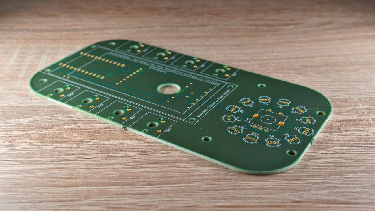
The most expensive part in this listing is the PCB. Unfortunately, it is a rather large PCB and as usual you cannot buy only a single board but need to order a minimum of 3 to 5. I ordered mine from aisler.net and if you are lazy and want to be sure, you can simply order the exact same15 PCB from Aisler (Warning: Read this footnote16) (this is not an affiliate link - unfortunately I do not get any share from your orders and the link is only there for your convenience). I have to admit though that this is my very first PCB design and I simply ordered from the local17 company I knew from work, so I did not exactly compare prices and I would expect that there are cheaper options. If you have experience with another PCB manufacturer or want to try a cheaper alternative, simply get my PCB design from the github repository for this project.
The PCB was designed in KiCad and since it also serves as the base plate for all the keys, it has much more space than is required for all the components. Most parts simply have a direct connection to an I/O pin of the Pro Micro, with the exception of the rotary encoder for the jog wheel, to which I added hardware debouncing with a set of two resistors and a capacitor per switch. Since I did not do much testing, I am not entirely sure if this was necessary, while at the same time, some additional capacitors to stabilize the LED voltage might have been a good idea (although I have had no problems so far). If you have improvements on my design (or just a different layout), I’d be delighted if you share it with all of us.

Speaking of the LEDs, there is one last thing to note about the electronics: For a standard USB port the Pro Micro should not draw more than 500mA and consequentially, one should draw somewhat less from its 5V pin. If you estimate 20mA per color per LED, you will notice that the LEDs can draw more than that if they are all on full bright white. There is nothing in the hardware design to prevent this, but my Arduino code limits the brightness to a rather conservative level. Keep that in mind if you write your own code for the LEDs and go to brighter settings with caution.
Finally, there is one more item that you need: The case. My version is 3d printed and you will find the STL files in the github repository or on thingiverse.com. So you either need a 3d printer or a creative different solution. I would also love to see some wood or metal cases - just be careful about the keycaps, because I always had printing my own keycaps in mind from the beginning, so the distance between the Cherry switches might not be standard.
If you go with the 3d printed version, you need to print the bottom, the top, eight keycaps, the knob for the jog wheel and a tiny plug that covers the access hole for the reset button (explained below). Note that my rotary encoder has a cylindrical axis with a slit in the middle. I think I have seen versions with a flat side instead, which might not fit perfectly in the 3d print, so either look for the right encoder or slightly modify the knob if necessary. All parts can be printed without supports and of course, if you want them to look nice, you should use fine settings like 0.1mm layer height. Mix colors to your liking, although you probably want a white jog wheel for the LEDs to shine through.
Oh, and a little note and credit on the rendered images of the PCB and the device: These are made in Blender, based on a 3d model exported from KiCad, which I converted using FreeCAD. Most of the components are from the KiCad libraries while I got the Pro Micro from the Spark Fun KiCad Libraries combined with a 3d model by Andrew Whitham.
Ok, have all the parts and the PCB? Then, solder everything! For most components, it should be obvious where they go because of their outline and, of course, you should attach the display after everything has been soldered as it would block access to the soldering pads of some parts. To help you keep track of your soldering, here is the list of components to solder in the order that I would recommend. I started with the backside - the one with only an outline for the Pro Micro as the only larger component. Do not start with the front (the one with outlines for the Cherry switches and the label for the display) as the Cherry switches might be a bit in the way when soldering other components. So, in any order you like:
Now it is time to solder the stuff on the front. In my opinion, it does not matter much with which components you start as they all have similar problems when it comes to aligning them. You might want to read my suggestions to each first and then consider your available tools like clamps and vises that you can use to hold the PCB and the components, so you can start with the one that is most problematic for you.
One more tip for soldering the LEDs: The distance between the solder pads of the LEDs is much smaller than for all the other parts and I did not manage to solder a single one of them without shortening at least two of its legs. Do not despair and do not try to remove the excess solder by dabbing at it with your soldering iron. Instead, continue as if everything went fine until all LEDs are in place. Then slightly increase the temperature of your soldering iron18 and use some desoldering wick to remove the excess solder. If you have never done this before, watch a few videos on Youtube and you get the idea. It is really that easy and much safer than trying to fix the problem in any other way.
If everything went fine and you did not yet do so:
Now it is time to mount the display. If yours is the same as mine, it comes with eight colored cables. You need to bend them in pairs of four to each side so that they go back under the display between the connector and the mounting screws (see image below). Thread them through the hole in the PCB and (if they are as long as mine) bend them into one loop before plugging them into the connector. Note the labels at the connector and on the screen. The order should be the same on both, but better make sure.
Finally secure the screen on the PCB with the four M3 screws from the backside. If the screws are a bit too long you can add small washers, but make sure that you can still close the case later.
At this point, everything should be ready. Before putting everything into the case, this is a good time to test the hardware. To do so, plug the Pro Micro into your computer, fire up the Arduino IDE and load the “harware-test” sketch from the “arduino” folder of my github repository. It should shortly show a circular test pattern on the e-ink screen and illuminate the LEDs clockwise in red, green, blue and white. You should also open the serial monitor where should see output when you press any of the Cherry switches, when you press the rotary encoder and when you turn the rotary encoder.
Everything went fine? Then if you just want to use my firmware, load the one from “arduino/inkkeys” onto the Pro Micro before continuing. However, if you want to play with the firmware and adapt it to your needs, you might want to attach the optional reset button now. You can thread it through a small hole in the case to have a reset button during development and later simply pull it out and seal the hole, if you want to.
To assemble the case, simply place the PCB onto the bottom part and push it onto the rods matching the holes in the PCB. Then place the top onto the PCB and push it down. Depending on the tolerance of your 3d printer and your taste it might already fit tight enough - if not, you can of course add some glue to fix it more permanently. Finally, simply push the big knob onto the rotary encoder and the eight keycaps onto the Cherry switches. If they make a squeaky noise afterwards, it is probably the side part of the cap. I liked the design in my limited design capabilities and sandpaper or a file should fix the problem, but I am also happy to see and share different designs.
At this point, there is a little hole at the edge with the reset pin header behind it. If you are done developing, simply pull out the reset button through the hole and cover it with the tiny “debug plug” part (same if you did not use it in the first place, obviously). This plug is deliberately designed to be a very tight fit, so you probably need some sandpaper to make it fit perfectly.
The Arduino code running on the Pro Micro is relatively simple with about 750 lines of code and I endeavored to properly comment most of it for once. If you just want to use it with my PCB design without modifications, you should only check if your rotary encoder generates the same number of increments per step and has the same number of steps per rotation, simply because I am not sure if they are all equal. Simply rotate the encoder and count the number of steps to get the number of steps in a full circle, which you need to set as ROT_CIRCLE_STEPS in the file settings.h. Also watch the serial monitor and check if each step generates exactly one event. If not, you need to adapt ROT_FACTOR as well (I would expect that 1 or 2 are possible other values besides the 4 for my encoder - but I do not really now that). If in doubt, you can get the exact increment from the hardware-test sketch.
If you just want to clone my device, you can skip the rest of this section where I give an overview of how the sketch works. If you want to adapt and modify it, you might want to read on.
As mentioned earlier, the device acts as an HID keyboard, an HID mouse and an HID consumer input device. This is actually very simple as there is already the great “HID project” library by Nico Hood, which allows for much more versatility than the Arduino core libraries for keyboard and mouse emulation while being almost as easy to use.
The key assignments for our device are stored as a sequence of HID events, which can be a keypress, a release or a keystroke (press and release without further discerning them) or increments by a specific number for mouse axes or the mouse wheel. Actually, you can combine events across the three HID device types (keyboard, mouse and consumer) and also insert delays. Since these sequences are implemented in static arrays19 and need to be stored for 9 buttons with press and release events each, as well as the rotary directions of the jog wheel, I have limited the number of events within a sequence to 10 due to the Pro Micro’s limited memory.
Speaking of limited memory: It also does not have enough memory to hold the entire content of the screen, so we need to stream the image from the controlling Python script directly to the backbuffer of the display. This is in itself not a problem, but for this e-ink screen to properly do partial updates, you need to send the image twice. You write your new image to the backbuffer, refresh the screen (so the previously shown image is now in the backbuffer) and you have to write the same image to the new backbuffer. The reason is simple: If the display should only update pixels that have been changed, it looks at the difference between the backbuffer and the currently shown image. So, to keep those consistent, you need to eventually write the new image data to both buffers, one before the refresh and one later to keep them the same. This may be very obvious to you now, coming from the perspective of a backbuffer, but if you think of a partial update as only writing a part of the image, you would be quite surprised at the next refresh when parts of the previous refresh vanish that you did not even touch in this new refresh.
Anyhow, since we do not have enough memory, we only use the low-level functions of the e-ink display library GxEPD2. So, in contrast to my wedding gift project, I cannot directly render text or draw shapes on the microcontroller, but directly write a pixel bitmap to the display, which I stream from the serial input (as explained in the next section).
The parsing of the serial input takes up most of the remaining code and the remaining libraries are quickly explained: There is the Adafruit_NeoPixel library to drive the LEDs and the encoder library by Paul Stoffregen, which handles the rotary encoder. This library uses interrupts on the two input pins attached to the encoder which is why I decided to debounce it in hardware. I expected to trigger these much more rapidly when rotating the wheel quickly, so I wanted interrupts without blocking my code by triggering the interrupts all the time because of a bouncy signal. The Cherry switches in contrast are directly connected to the inputs20 (using the Pro Micro’s internal pull-up resistors) and are simply read periodically and naively debounced in software.
In order to set key assignments, receive key events, drive the LEDs and update the display, I have created a compact and simple serial protocol. If you only intend to modify my Python script to your needs, you might get away with skipping this section as this protocol is encapsulated by the “inkkeys” module in my Python script. However, if you plan to modify a bit more of my script, you should probably know how it talks to the device and if you want to write your own driving code entirely, the following are the basics.
I will write the following from the perspective of the device, so an “incoming message” is data sent from the Python script on the PC to the device and an “outgoing message” is sent from the device to the PC. Each message is a sequence of ASCII-encoded characters, terminated by a carriage return character. The only exception is binary data for the screen as explained below. Incoming commands always start with a single letter denoting the command, which can be followed by command-specific parameters separated by spaces.
1
A <KEY>[p/r] <SEQUENCE>
Assigns a function to the key <KEY> (see below) being pressed (p) or released (r). p and r are not used for the jog wheel. The sequence syntax is defined below and may contain up to 10 events. If you need a more complex sequence, consider doing this on the script on your PC instead and triggering it through the key event reported via serial.
A <KEY> can be the digit 1 to 9 or the two-character sequence “R+” or “R-“. 2 to 9 are the Cherry switches, 1 is pressing the rotary encoder (jog wheel), “R+” is turning it clock-wise and “R-“ is counter clock-wise.
The <SEQUENCE> can be empty to not send anything to the system but still report to the controlling script via serial, so it can trigger a callback in the Python script. To send keyboard or mouse events you can define up to 10 <EVENT> strings, separated by spaces.
Each <EVENT> can be a delay, denoted by d<TIME> with <TIME> being an integer number representing the delay duration in Milliseconds. Note, that the device will be unresponsive during the delay, so you should not use it to extensively. More commonly, you want to set <EVENT> to be associated with a keycode to be sent via USB. This takes the form <DEVICE><KEYCODE>[p|r|i<NUMBER>] to send the keycode <KEYCODE> on <DEVICE> with a press (p), release (r) or increment (i) by <NUMBER> (-128..+127) event. If you use neither “r”, “p” or “i” it will be a simple keystroke.
The <DEVICE> can be c, k or m and determines whether this keystroke is sent as the consumer keyboard (c), the regular keyboard (k) or the mouse (m). The <KEYCODE> is just an integer (decimal!) number representing a key as defined in the HID project. If the <DEVICE> is set to “mouse”, the keycode could also be “x”, “y” or “w” to represent the x and y axes of the mouse or the wheel (w). In this case you should use “increment” as the event type.
1
D <NUMBER> <NUMBER> <NUMBER> <NUMBER>
Sends image data to the display’s backbuffer. The parameters define x, y, width and height of the area on the screen to be written to. After this command you have to send binary data of exactly the length width*height/8 and then call the “R” command (see below). Since the Pro Micro does not have enough RAM to hold the entire image and since it needs to write the entire image again after refreshing the display to update the backbuffer of the display (otherwise subsequent partial refreshes would not work, see previous section), it needs to be able to stream the data again after the refresh. Therefore you need to send exactly the same binary dataset twice (unless you intent to always send the entire screen). So, after calling “R” (see below), you need to send this “D” command again, followed by exactly the same data. After that, you should call “R o” to turn off the display power to prevent degradation. Also note, that the width of the written area needs to be a multiple of 8 (no partially used bytes) and that the display is rotated by 180°, so you want to rotate your image accordingly.
1
I
Requests information on the device and is used as a handshake to make sure that the right device is at the other end. The response contains hardware details like number of LEDs or display resolution and might be helpful to write Python code that works even with new hardware layouts (which I hope to see from users modifying my design).
1
L <RGB> <RGB> ... <RGB>
Send RGB hex codes (six digits: “rrggbb”) to set the individual LED colors. For 12 LEDs you need 12
1
R [f/p/o]
Show the image data that has been transferred in a partial (p) or full (f) refresh. Remember to resend the entire data after this command, so the backbuffer can be filled for subsequent partial updates to work properly. After that, send this command again with the option “o” to turn off the power to the screen to avoid wearing it out. So, the total sequence to partially refresh the entire screen would be “D 0 0 128 296”, <4736B of image data>, “R p”, “D 0 0 128 296”, <4736B of image data>, “R o”. The device will be unresponsive during the refresh and will respond with “ok” when it has finished.
If you prefer some ready to use examples (like I do):
1
2
A 2p k59p
A 2r k59r
Assigns the key A to button 2 by assigning press and release event of keycode 0x3b = 59 to the keyboard device.
1
2
A 2p c205
A 2r c176
Uses media keys to start playback when pressing button 3 and stopping playback when releasing the button by sending the consumer keyboard keystroke for play and pause with each event.
1
A 1r k225p k23 k225r k8 k22 k23
Lets releasing the key on the rotary switch print the word “Test” (including using shift for capitalization).
1
2
A R+ mwi+1
A R- mwi-1
Lets the rotary switch act as a mouse wheel.
1
2
A R+ mwi+5
A R- mwi-5
Lets the rotary switch act as a fast mouse wheel.
1
2
A R+ k79
A R- k80
Lets the rotary switch press the left or right arrow keys.
1
L ff0000 ff0000 ff0000 ff0000 ff0000 ff0000 00ff00 00ff00 00ff00 00ff00 00ff00 00ff00
Makes one half of the LED ring red and the other green.
For those of you who just want to build and use this device, this is the important part and this is the part where you actually have to code something. You will find the code I used in the video and which I plan to use on a day-to-day basis in the repository in the “python-controller” folder, but there are so many ways you could use this and I am sure that I will find some bugs while using it in production that the code will see a few updates and revisions over time.
Most importantly for you, though, is that it is specific for my needs and only tested under Linux. I think that most of it should run on Windows and MacOS, too, but I have not tested it21. Hopefully, everything works out of the box (except for the volume control feedback based on Pulseaudio, which certainly won’t work outside Linux), but you should still expect to fix and improve a few things if you are the first to try it. On the other hand, I would be very happy to merge some cross-platform improvements from the community. Besides these problems, you still have to implement your desired functionality, but I tried to not make it too hard.
When you look into the “python-controller” folder, you will notice four files and a few folders.
controller.py is the main code which is supposed to be run in the background.modes.py defines the function of the keys, the display and the LEDs in different modes (explained below).mqtt.py is a class that handles the MQTT communication specific to my setup.processchecks.py contains some helper functions to retrieve the currently active window and the list of running processes from the OS.font contains fonts I use or found useful, Munroe and Silkscreen under the SIL OpenFont licence. Since the e-ink screen has a low resolution and no grayscale, I highly recommend to look for pixel fonts if you want more alternatives.icons contains a set of icons from Bootstrap. They were simply converted in bulk from SVG and are not perfect, but a good start.inkkeys is a module that encapsulates the serial communication to the device and adds a few functions.This is a Python 3 script, so from the command line (or whatever weird substitute you Windows guys use) you would call it as python3 controller.py. It should give some output as it searches for the serial connection to the device and should keep running until you hit Ctrl+c to disconnect from the device and Ctrl+c for a second time to stop the script. If you want more output for debugging and understanding what it does, you should set the variable DEBUG to True in the fourth line of controller.py.
You probably do not need to touch the other settings, but only need to look into them if your Pro Micro is somewhat different or if you use a different microcontroller. VID and PID are vendor and product id to identify the device. If this does not work, you might want to check if they are different in your case (use lsusb on Unix systems), but you can also just set SERIALPORT to the right port, so the script won’t search for the device but just use the correct one.
Also, you will find an IP address in line 31, which you probably want to replace with None for now. This is the connection to my MQTT broker. If you want to do something similar, you can look into it later, but you should get the basics running first. To do so, you will need a bunch of libraries. You will not need all of them eventually if you do not use exactly the same functionality as I do (like MQTT or OBS websockets), but I would recommend to install them anyway to make my examples usable and then strip them down later. These are: obs-websocket-py, paho-mqtt, Pillow, psutil, pulsectl, pyserial. On top of this list, there are system-specific modules to check the active window: python-xlib (Linux), win32gui (Windows) or appkit (MacOS). So, on a Linux system, you should be able to use “pip” on the command line to get everything22 ready: pip3 install obs-websocket-py paho-mqtt Pillow psutil pulsectl pyserial python-xlib
At this point you should be able to start controller.py without missing libraries. It will check if the device correctly responds to the I command (see above) and if it does, the script will enter an endless loop in which it checks which processes are running and which window is in focus. Depending on these, it will choose a “mode” for the device.
1
2
3
4
5
6
modes = [\
            {"mode": ModeOBS(), "process": "obs"}, \
            {"mode": ModeBlender(), "activeWindow": re.compile("^Blender")}, \
            {"mode": ModeGimp(), "activeWindow": re.compile("^gimp.*")}, \
            {"mode": ModeFallback(mqtt)} \
        ]
These “modes” are assigned to processes and windows in an array in line 33. Each entry is a dictionary with the key mode set to the instance of a mode (more on that later) and optionally the key process, naming a process, or the key activeWindow with a regular expression to match a window. The script will iterate over these entries and pick the first entry that matches. If process is set, the entry will be used if a process with exactly the same name is running (does not need a window and if it has one it does not need to be focussed). If activeWindow is set, the entry will be used if the currently active window matches the regular expression in activeWindow. If neither is set, the entry will always be used, so this only makes sense as the last entry as a fallback mode.
So, in the example above, the mode ModeOBS is used if OBS is running, even if it is just sitting in the background. If OBS is not running, ModeBlender is shown if a window starting with the name “Blender” is active and ModeGimp will be used if a Window starting with “gimp” is active. If neither OBS, Blender or Gimp are found, it will fallback to ModeFallback.
What are these modes and how do you get more of them? Each mode is a class defined in modes.py. The minimum version looks like this:
1
2
3
4
5
6
7
8
9
10
11
12
13
14
15
16
17
class ModeMinimum:

    def activate(self, device):
        #Called when the mode becomes active
        pass

    def poll(self, device):
        #Called periodically to allow the module to poll something
        return False    # No polling in this example

    def animate(self, device):
        #Called periodically for animations.
        pass

    def deactivate(self, device):
        #Called when mode is deactivated
        pass
The typical use would be to set some icons and key assignments in activate and maybe clean up a few things when deactivate is called. poll is called at least once and you can return a number in seconds to tell the main script to call it again after a given time. This can be used to poll some status (from a website, a smarthome device, the number of mails in your inbox, etc.) periodically. Return False if you do not need it to be called again. Finally, animate is called about 30 times per second and supposed to be used for LED animations. This is probably way too often for normal status polling, so you should only use it for that. Quite often you will just call device.fadeLeds() here to use the fading animation of the inkkeys module, but more on that later.
These modules can be as simple as assigning a few keys and showing icons for them, but they can also be a rather complicated Python scripts using MQTT or other modules to interact with other software and devices to provide LED animations, changing status icons and complex activities on a key press. I have sorted my examples in modes.py in order of complexity:
ModeBlender only shows a handful of key assignments23 with a few icons. Start here.ModeGimp adds on ModeBlender by using a callback function to react to presses on the jog wheel. In this example, the callback simply switches the assignment and the label for the jog wheel rotation to allow for multiple tools.ModeFallback adds even more. It uses the MQTT class (defined in mqtt.py and passed by controller.py) to poll a CO2 sensor and show an alarm on the LEDs if it is above a specific threshold. It also polls the state of a lamp in my office and shows the appropriate icon on the screen (lamp on/off) and sends a control command to toggle the lamp if the right button is pressed. It also has a demo button that does a full refresh of the screen, adds the URL of this blog and shows a rainbow LED animation. I used this for photos and videos, but kept it in here as an example.ModeOBS is probably interesting to quite a few of you, but possibly the most complex example. It uses the websockets plugin in OBS and the obs-websocket-py Python library to control OBS to switch scenes, toggle sources and show the current state on the screen and the LEDs.You should look at the examples to learn how to set up your own modes. You will find that they make heavy use of the “inkkeys” module which offers several functions to control the macro keyboard without manually putting together the serial commands. To use it, you instantiate a Device and connect it to a serial port. This is all done in controller.py for you (check inkkeys/device.py if you want to use it yourself) and the instance is given to your mode class as a parameter to each of its function calls. With this instance, you can assign keys, control the LEDs, send images to the display, send icons for a specific button, send text to the display, register callback functions for specific key events and (periodically) call fadeLeds to fade out the last set LED state. Note, that the library also takes care of resending the display content and turning off the display after you called the updateDisplay(fullRefresh=False, timeout=5) function.
You should be able to imitate the usage of the example, which I think will be the fastest method to get going. If you want to know in detail, what each of the functions of Device do, check out inkkeys/device.py where they are defined and if you need to look up constants for keycodes, mouse axes, buttons etc., have a look at inkkeys/protocol.py where they are all defined.
There is only one problem regarding the keycodes: They are defined for an US keyboard layout, so your keycodes might send a different symbol or command than their names might suggest if you are not on an US keyboard layout. There are three options:
setxkbmap).Now it is time to experiment with the inkkeys module and to write your own “modes” or even rewrite the entire thing. When everything you want is working as expected, you should set the script up to automatically launch when you log into your desktop environment. I did this by creating a little shell script with a cd /home/dicon/[...]/[...]/python-controller to change to the correct working directory, followed by python3 -u controller.py | ts >> inkkeys.log. The -u disables buffering of the Python output, so it can be redirected to a log file, which is done by >> inkkeys.log. The | ts pipes all output to the command line tool ts24 which adds timestamps to each line, so if something goes wrong you have a nicely formatted log file to start searching for the problem. In the end, I simply add this script to the desktop environment’s list of startup program.
I would love to see a little community around this device. I was surprised how many recreated my LED cube even though I did not provide a step-by-step guide and did not really design it to be recreated. It was not that well documented and people ended up helping each other on GitHub and Reddit. I want that here, too, although I cannot assist every single one of you and I only provided a basic software with some examples. If you recreate the project and maybe have added something that might be useful to others, please come to r/thereoughtabe on Reddit for support, discussion or showing designs, cases and ideas. For specific code changes, use the issue tracker on GitHub for bug reports (actual bugs - not “how can I …”) or to contribute your code, case design or “mode” to the project (for the latter, I would suggest to add a new directory “modes” and adding a py-file with a meaningful name to keep some structure while the examples outlined here remain one level above). I also appreciate to learn about materials hosted by yourself or on other sides, so I can link to them from the ReadMe files on GitHub for other users to find.
If you like this project, please share, like, subscribe, retweet, pin, follow, upvote or do whatever verb your favorite network’s marketing genius came up with for showing your appreciation (links to my accounts are at the bottom of this page). You can also announce this project with a bullhorn on your local market square or send a postcard to your grandma about this website if she is a tech geek25.
I hope you enjoyed it and I am looking forward to see your build or modifications.
The open source alternative to Photoshop. ↩
Those shortcuts in Gimp actually depend on the language setting. Alt+B is for “Bild”, the German word for image. So, if you use Gimp in another language, the shortcuts will be slightly different. ↩
That’s the advantage of wheels. There is a reason that you use a steering wheel to make sharp turns while parking while also precisely switching lanes with subtle direction changes on a highway. You would not want to o this with a joystick or a mouse - and I would not want you to, either. ↩
Actually, in my internal numbering, it is the first button with the other eight being number two to nine. ↩
Not that I couldn’t see the lamp directly and needed an additional indicator. ↩
Open Broadcaster Software, a software to mix live video streams from different sources. I use it in lectures and video meetings to switch between camera angles, to share the screen of my phone or to show slides. ↩
…or to show off. I mean, that is what RGB LEDs are for, right? No, I am not a gamer who needs an RGB mouse, RGB keyboard, RGB case and an RGB toilet seat, but I cannot deny that those rainbows are fascinating. ↩
This is also one of the key features of the Arduino Leonardo, which uses the same chip and might be better known to those who stick to Arduino-branded boards. ↩
There is actually a small risk that this might re-introduce communication delays and make it less snappy, but as long as the Python script is able to receive the serial data fast enough to keep a buffer from overflowing, this should be minimal - and there is certainly something wrong with your script if a Pro Micro can flood your script running on an all-mighty desktop CPU. ↩
I am a physicist. I know how electronics work in theory, but I have no insight into practical applications. This ignorance of practical details can be worse than not knowing anything at all. ↩
You can pick whichever response function and noise level you like. I would suggest to use the ones for PCB mounting. If you watch my video closely, you will notice that I did not use those, because I did not know of the difference when I ordered them. I think the keys would be better aligned if I use the PCB-mount variant. ↩
Most of these prices are for buying few of these components from amazon. They are much cheaper if you buy them in bulk or at least add them to an order from an electronics shop without paying individual shipping and packaging. ↩ ↩2 ↩3
On my device, I actually use M3 4mm screws with two washers to fit the screen to the PCB. This is only because I did not have any shorter screws at hand, so if you need to buy them, you should get 3mm screws instead. ↩
This is for three PCBs from aisler.net. ↩
Not exactly the same. The version I ordered and which you see in the video had too small holes for the screws and I had to file them open. This should be fixed in revision two of the board in the link and in the repository. ↩
Sorry, had to add this note on 29th December 2021 when a user told me that there is a problem with this link. Apparently, new revisions by other users have been mixed up in Aisler’s system, so that the link is currently pointing to an entirely different PCB that I do not know anything about. It seems like you can just select revision 3 instead, but there seems to be something strange going on over there. ↩
Aisler is actually from the Netherlands, which is a different country. This may seem weird for non-EU readers, but I could actually walk there from my work place in Germany without even planing or preparing anything. If you do not watch out for it, you might not even notice the border. Who does not appreciate such a harmonious and free world? Maybe someone for whom walking is not an option because he is living on an island… Some North Sea Island perhaps… ↩
Don’t worry if you cannot set a temperature on your soldering iron. In this case it is probably hotter than it needs to be anyway. ↩
Yeah, I was a bit lazy there. Happy to receive a pull-request using dynamic allocations. ↩
With 8+1 keys, there is no point in using a key matrix just to save three GPIO pins that would not be used otherwise anyway. ↩
To be honest, I have a Windows and a Mac at hand, but setting up Python on Windows is such a pain and feels so out of place. The Mac is for iOS development from my employer and I honestly never understood what people like about Macs. Besides, the community can do some of the work - that increases engagement or something ;) ↩
It is sometimes difficult to see which libraries were installed with your Python distribution, which were installed manually and which were installed months before this project as a dependency of an entirely different package. If I missed a library I am sorry, but you probably know how to install it if it pops up as an error. ↩
This is just and example. No one in their right mind would want to use a macro keyboard for Blender. It is so keyboard heavy that you want to keep one hand on the normal keyboard and the other one on the mouse. It is hard to start learning all the shortcuts, but it is worth it, trust me. ↩
You might need to install it. sudo apt install moreutils in case of Linux Mint. ↩
Ok, you would do one of the aforementioned marketing verbs if she is a tech geek. Still, postcards are nice, too. ↩