
05 April 2021
As all package delivery services in our area have conspired to ring our doorbell just when the kids are having their afternoon nap I decided to smarten up our doorbell. To do so, I created a small PCB that goes into our in-house phone to disable it, trigger other IoT devices if someone rings the bell and to trigger the door opener. You can get an overview in the accompanying video or just read the article.
Well, I pretty much said it in the introduction. It is a little circuit that can disable our dumb doorbell, so it does not awaken the kids. In order to not miss any packages or visitors, it detects if the bell should be ringing and relays the signal, so we can be notified by other means. And, finally, it allows us to trigger the door opener without pressing the button on the in-house phone.
The board connects to our local Wifi and exposes these three functions via MQTT. This way it can be integrated into most open home automation systems to interact with all the smart things and IoT stuff. Some use cases are very obvious: Silence the bell and get notified through a notification on your phone or a flashing smart bulb even in rooms where you would not hear the bell or while wearing headphones. You can also open the door1 from your phone while on your way to greet the visitor without a detour to the button on the wall or you can let the lady in the tube2 (Alexa) announce that there is someone at the door.
Other use cases came up when the system was already in place: We have some facade lights that now fade on for a minute when the bell is pressed (yes, I admit that this is more about boasting than solving any serious problem) and the problem of delivery guys getting trapped by our child-proof lock on their way out is solved by a simple press on the phone. When the pandemic is over, I can see how we automatically trigger the door opener for anyone who rings the bell during a garden party or you could turn on the sprinklers and close the roller shutters to make it clear that you are not prepared to receive guests.
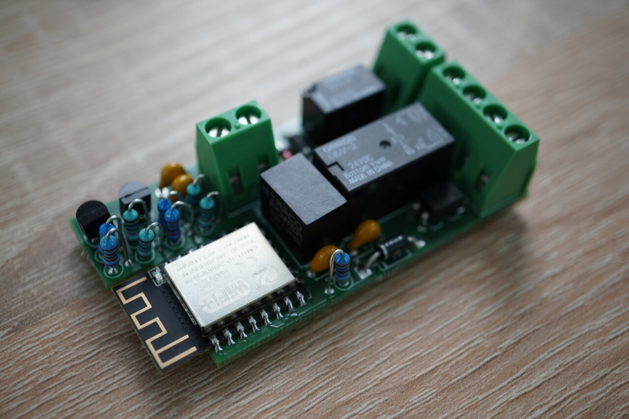
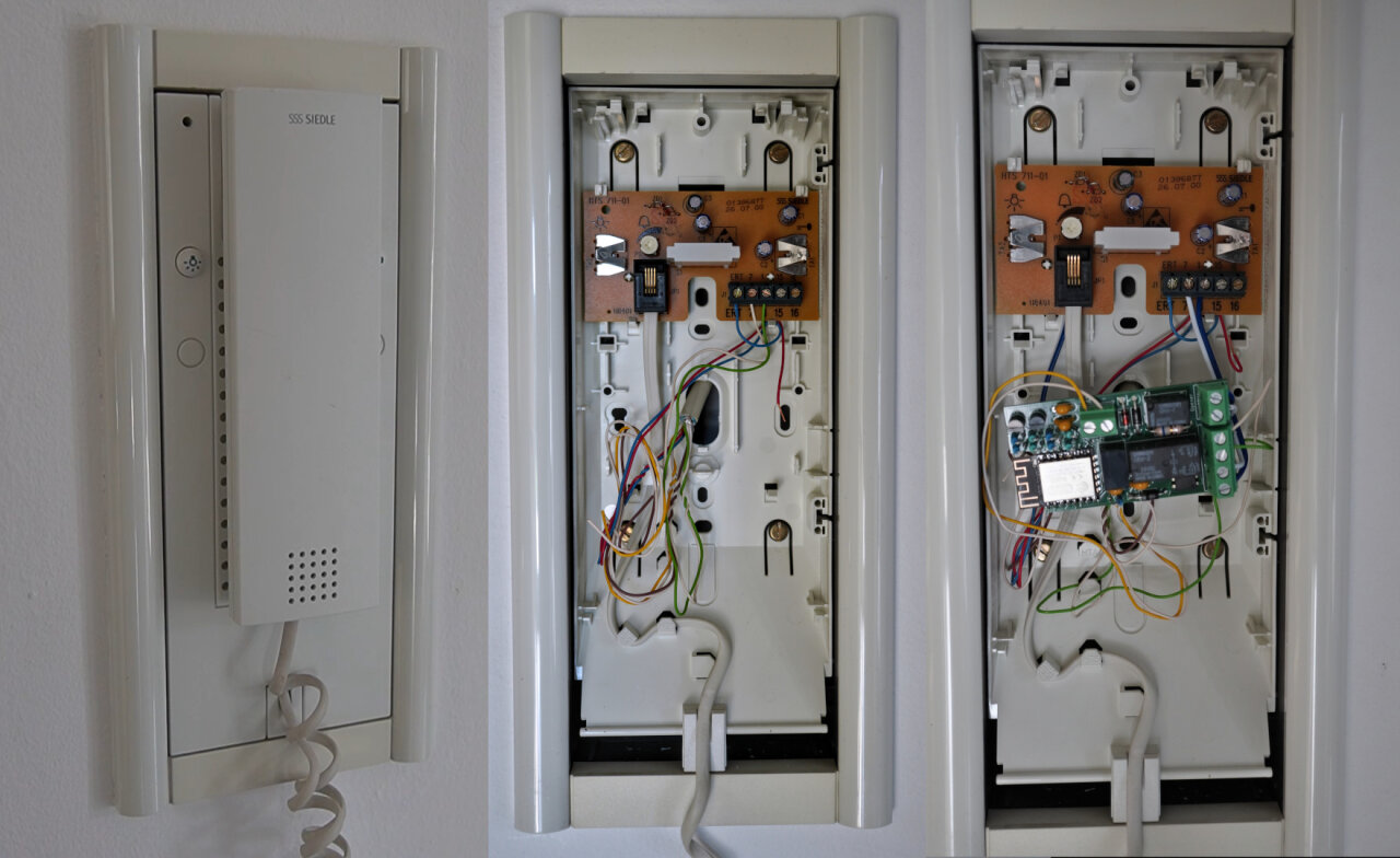
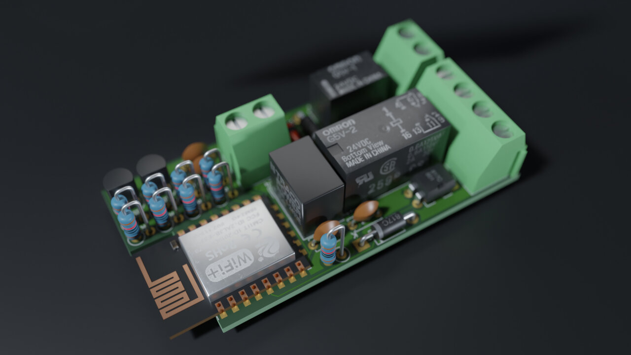
For my version of a smart doorbell I once again shied away from SMD soldering and designed a compact PCB that holds everything with mostly THT components. It is small enough to fit into the housing of our in-house phone, where it sits between the outside station and the board of the in-house phone, which it can conveniently disconnect completely.
If you are now saying “I want that!”, I have bad news. As always I am sharing all my designs and software, but the electronics are quite specialized to our doorbell system. When I said that it is a “dumb doorbell”, I did not mean that it is just two wires that are closed when someone presses a button outside. It is a Siedle “1+n” system, which means (besides being obscenely expensive for what it is) that there are indeed only two wires going to “bell” part of the system, but those are going to an in-house phone which allows to speak to visitors and controls the door opener. So, we are not only dealing with a simple switch across two cable but with two cables that supply the phone with power and with the ring signal, the speech and the door opener modulated on top of the supply voltage. Also, to supply my board with power I used a 24V3 DC output from the Siedle power supply, which is not available on newer 1+n system.
So, the point is this: You can only take my design if you really have exactly the same system and you should really know what you are doing. If you do not have the same system I hope that you can use my project as a source for your own design. …and if you do not know what you are doing, please do not mess with your doorbell system in any case as you might just fry it.
If you still want that PCB, you can find the diagram below, the KiCad designs on github or you can directly find the exact PCB I ordered at Aisler. As I said, it will probably not do you much good, so I won’t even bother with a BOM. Let me instead explain the individual parts of the circuit, so you can adapt the design.

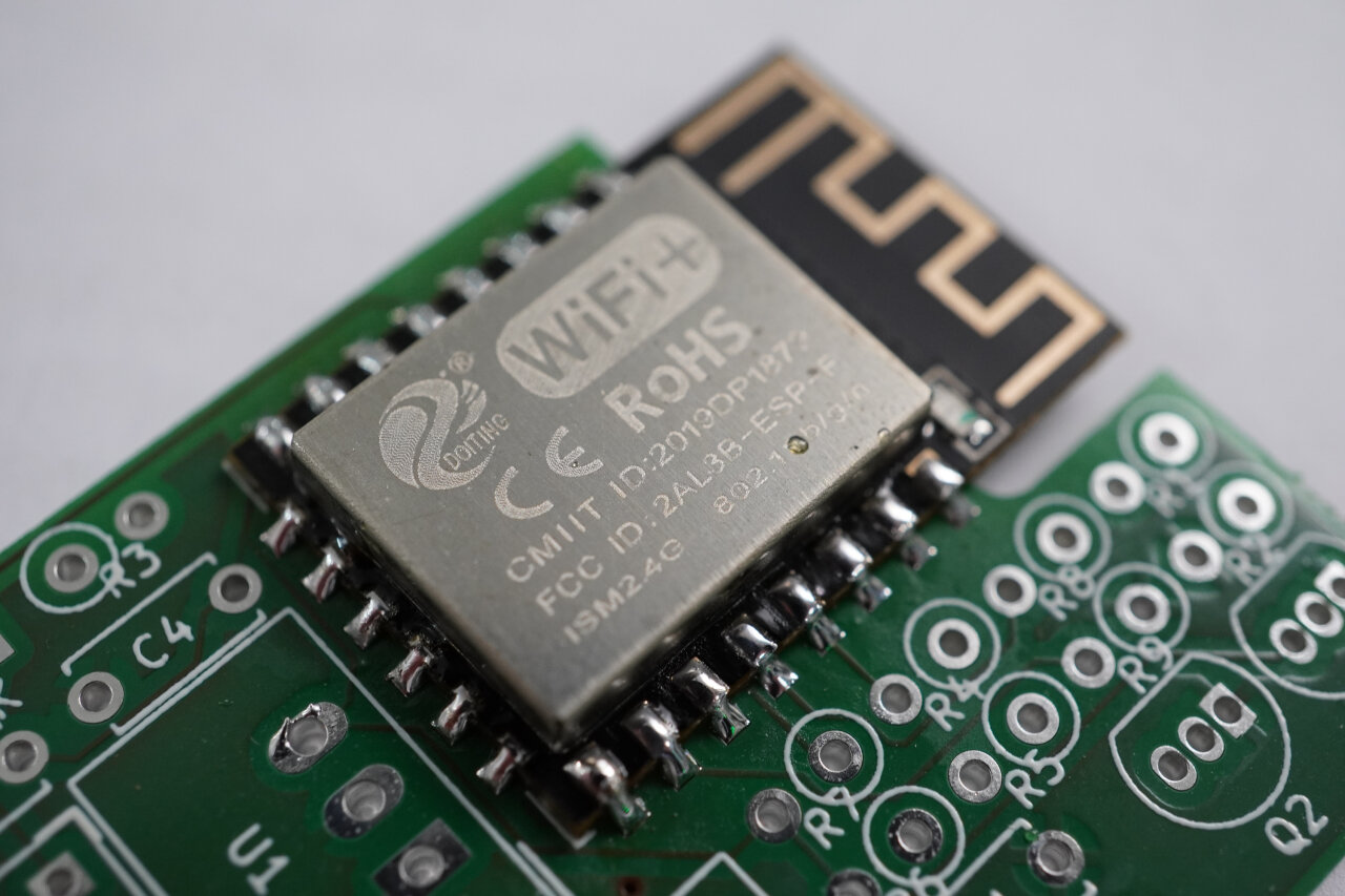
Let’s start with the heart of the board, the ESP8266. This is actually an exception from the THT components and my first SMD component that I ever soldered. It was easier than expected, so maybe in the future I will try more along that line. As I wanted to be compact, I did not go for a full-fledged development board but for the ESP-12F.
The downside of this is that you have to take care of a few things yourself if you are only used to the Arduino-experience of plugging in an ESP8266 to your USB port and start flashing it. This thing does not have a USB port, does not have a power converter and does not even start in a proper operational state if you only provide a voltage. Instead you need to make sure to pull specific pins high or low to tell it whether it should be ready to be programmed or run its code. In other words, RTFM or your design will fail like my first one did4.
Another important aspect of this is that you need to think about how to update the software of your ESP after you soldered it onto your board. Typical Arduinos and ESP developer boards can simply be connected via USB even when already integrated into another project, but with the ESP-12F you need to think ahead or you are stuck with the bugs from the Arduino code you last sent to the ESP before soldering it. One obvious option is to include a USB port, boot buttons and the required logic for programming in your PCB design, but besides being a more complicated design it will still be pretty annoying after you have installed the PCB in the case of an in-house phone.
Instead, I found that over the air (OTA) updates are insultingly simple to implement and so convenient that I might need to add them to a few other projects. So, I need to remember flashing my Arduino-code onto the ESP once before soldering and can subsequently update its software while it is connected to my network. You just should be careful not to break OTA with a new version and you should have a fallback if your Wifi changes or is unavailable. In this case, the smart doorbell circuit opens its own access point with a separate password if it is unable to connect to my normal infrastructure.
Oh, and if you are wondering about the first programming without a USB port: I used a snap-in pin programmer board, but there are also plenty of instructions on the web on how to do it with a simple DIY setup using any USB UART adapter or an ESP/NodeMCU developer board.
Since the ESP-12F does not have a voltage converter, you need to supply it with exactly 3.3V - and 3.3V only5. So, instead of just hooking it up to a USB cable (which I would not have available inside the in-house phone anyways), I needed an alternative. First, I thought about using the same power supply as the phone, which comes from the two wires from the outdoor station (wires 1 and 7 on a Siedle 1+n system). Unfortunately, I am not entirely sure about the voltages and variations that could be expected from these wires as they significantly change voltage if someone rings the bell (more on that later) and since other things are modulated onto that voltage as well.
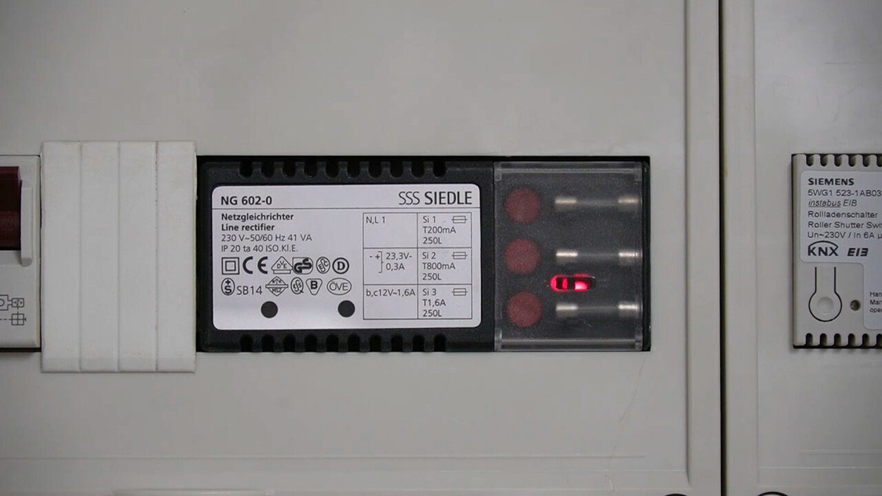
Instead, I found a very simple solution that happened to be readily available: My Siedle system is a bit older and used a power supply with a 12V AC output and an additional 24V DC output which was only used by the outdoor station. Interestingly, when I had to replace the outdoor station (death by corrosion and a spider’s nest), I found that the new outdoor station only uses the 12V AC supply, so I would not be surprised if you would not find these 24V on newer power supplies. In my case, it was sitting in my fuse box next to the cables to the in-house phones and the outdoor station with each cable having several unused leads. So, I simply hooked up the 24V to two unused leads to the in-house phone and added a 24V to 3.3V voltage converter (a TSR 1-2433) to my PCB.
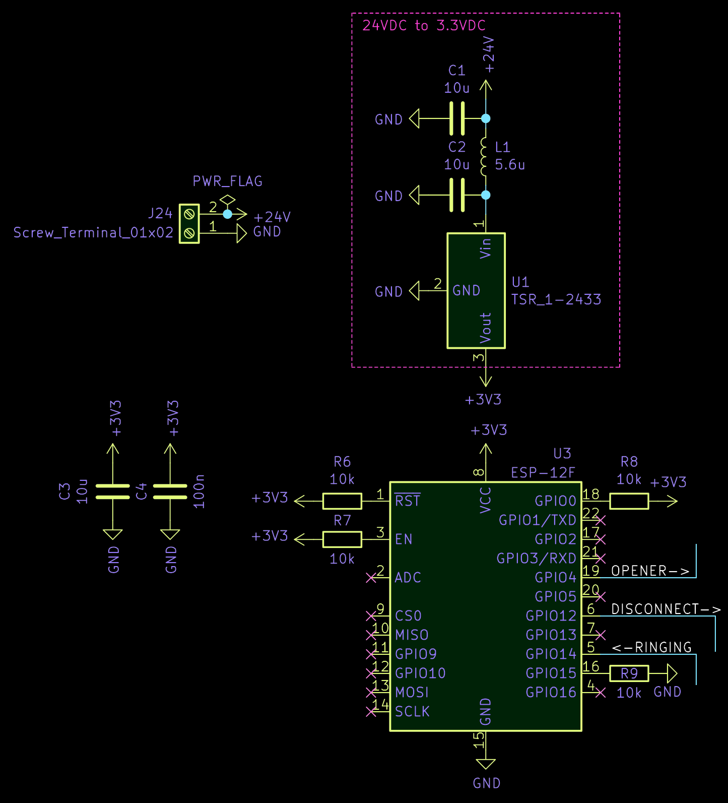
The additional capacitors and the inductor are the filtering recommended in the datasheets of the TSR 1-2433 and the ESP-12F. After all, I want this system to run unsupervised for many years and not have it die or act up due to a random voltage spike.
Next part of the circuit is its first feature: Disconnecting the phone from the two supply wires to disable its bell. This is a basic circuit to drive a simple relay through a transistor as you can find it anywhere on the web. Only specialty is that I am using a G5V-2-DC24 relay, which is a 24V relay6 that operates two switches at once. It would certainly suffice to disconnect only one cable from the phone, but as I was not entirely sure how the modulation works I did not want to leave the phone hanging on the other wire.
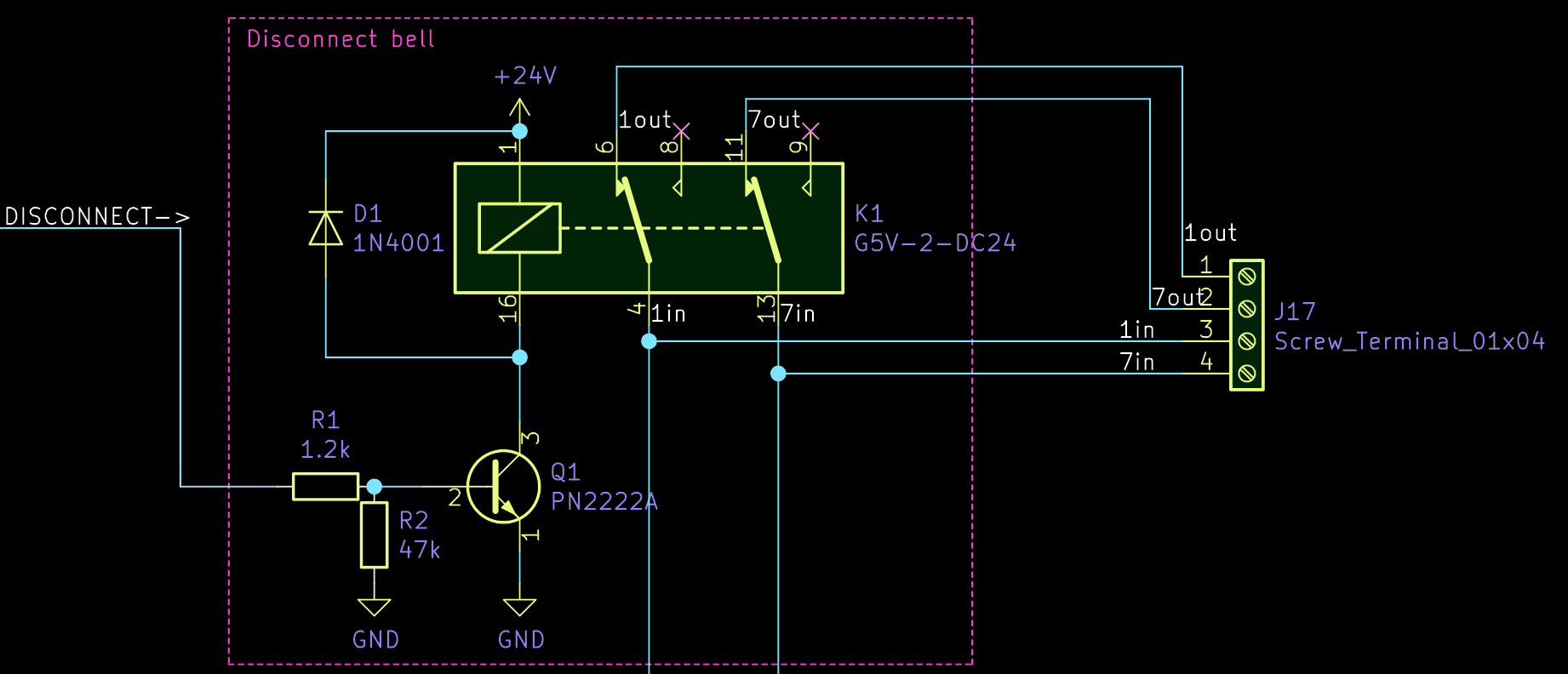
What I have not mentioned is that there is an additional dumb button attached to this bell for people who have already entered the garden (this is the ERT7 connector on the original PCB of the in-house phone). So, to make sure that it is not working either and to avoid some unexpected voltage drops from the ERT button (directly connected to the power supply) across a board that has been only half disconnected, I simply disconnect both.
Triggering the door opener is just as simple as adding another relay. But instead of disconnecting anything, this one connects the two contacts that would normaly be connected by the door opener button on the in-house phone. This way, I do not even have to know how this information is modulated onto the 2-wire system with the little downside that the ESP needs to shortly reconnect the phone in order to trigger the door opener. But since this can all be done by my Arduino code, I do not even notice this little detail in everyday use.

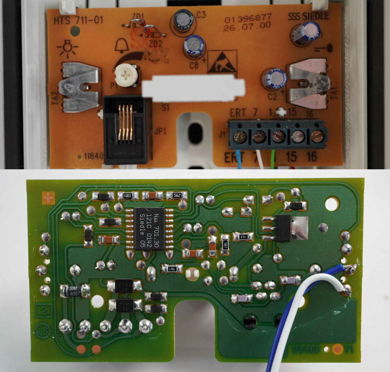
The slightly more annoying detail of this approach is that you need to connect the relay to the contact of that button. So, you need to disassemble the in-house phone (which to Siedle’s credit is very easy) and solder cables to these contacts of the original PCB. I do not have to say that this will void your warranty and I already mentioned that the Siedle stuff is absurdly overpriced, so don’t mess this one up.
Finally, the really tricky feature is detecting the doorbell, because this cannot be done by simply checking if a contact has been made. After all, we only have two wires from the outdoor station with a lot of information in them on top of the supply voltage. As you can find across various forums on the web, these two wires provide 18V if the doorbell is idle and the voltage rises to 24V if the system is ringing. So, we need to detect that.
Luckily, I found a post on the ioBroker forum by “Eisbaeeer” in which he describes a solution that is so simple and elegant that this part of of the circuit is even simpler than controlling a relay. So, he really deserves credit for this and if you want to know what he is currently up to, check out his page at www.kidbuild.de, his Youtube channel or his Instagram feed.
So, behold the ringing detection circuit:
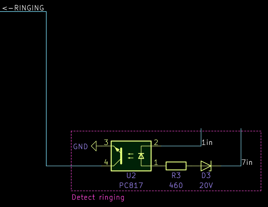
Yes, it is just a 20V Z-diode in reverse orientation and an optocoupler. If 18V are applied to it, it blocks any current and nothing happens. But at 24V it exceeds the diode’s breakdown voltage and the optocoupler can connect an (internally pulled up) input of the ESP to ground.
The Arduino code on the ESP connects it to my local Wifi and exposes all functions via MQTT. You can find the code on github and you will find that a relatively large part is just fallbacks to make sure that the OTA function remains available under any circumstance. Once you see past this part which somewhat makes the main loop hard to read, you will find that the main logic for normal operation is executed in its own loop function, called “normalLoop()”. From there, it should be easy to read. Just make sure to set up your Wifi credentials and a unique password for the fallback Wifi if you want to adapt my code.
The code exposes the following MQTT topics:
smartbell/housephone/set. The state of the phone will be published in the same way to the topic smartbell/housephone.smartbell/opener.smartbell/ringing.smartbell/ota the OTA update mode can be started. (Not required if the fallback Wifi hotspot is used.)To make sure that I do not forget to enable the bell again and to avoid that a break-down of my home automation system leaves the bell in a disabled state, the Arduino-code will automatically re-enable the in-house phone after three hours, which is also published to smartbell/housephone.
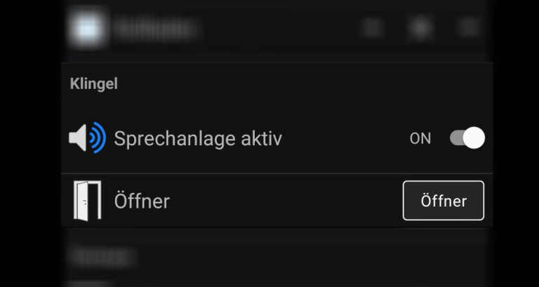
To control everything from my smartphone, receive notification and trigger other devices by the doorbell, I have integrated this into my OpenHAB system using its MQTT binding. But it should be very easy to integrate this into any other MQTT-enabled system.
Unfortunately, as I said before, I doubt that it is a good idea to just copy my PCB. But I really hope that you get a few ideas and that the schematics with the source code help you to pick the pieces that you need for your system and your specific needs. Just make sure that you understand how each of these pieces works.
For many of these examples you need to understand that the door opener triggers the door to our garden which you need to cross to reach the house. With all my IoT toys I have to say that the door to our house is still a high quality mechanical lock. In my opinion, motion detectors, contact sensors, presence detection, silent alarms and cameras are great, but if they are all on a network that is reachable from the street it is good to know that there still is a mechanical lock. That’s true two factor authentication. ↩
Strong podcast recommendation: Grumpy Old Geeks ↩
Actually, it says 23.3V on the power supply. Not sure why, but I have 24V in mind here, but this little difference does not matter anyways. ↩
You can see the faulty PCB featured in a 4 hour special on how to render a KiCad PCB in Blender. ↩
Four volts shalt thou not count, neither count thou two volts, excepting that thou then proceed to three point three volts. ↩
Of course a 24V relay - why waste the converted voltage at a high current on the relay’s coil. ↩
ERT stands for “Etagenruftaster”, which means “floor call button”. ↩