
13 January 2022
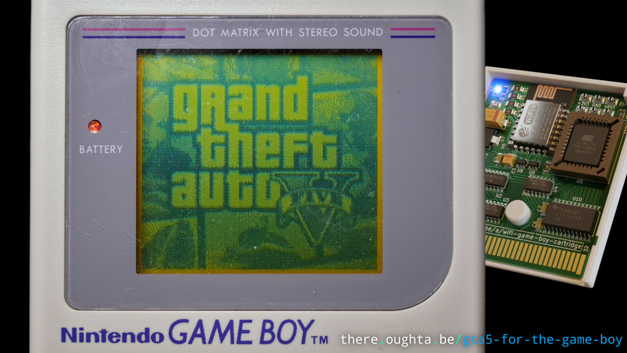
When I presented my WiFi Game Boy cartridge a few weeks ago, I only had very few simple text-based demos. This post and especially the accompanying video now deliver more. In fact, I might have gone a bit too far, as I managed to stream full resolution video and even play games via WiFi. But see for yourself:
So, as usual, you have two alternatives to start here: Watch the video or read the article. If you are just curious and want to see what I did, definitely check out the video. If you want to understand exactly how it works and if you want to reproduce it or find tricks for your own projects, go for the article and the linked code. In any case, if you have not seen the previous article and/or video on the cartridge itself, you should start there.
Ok, so you have either built the WiFi cartridge yourself or want some code for your own Game Boy trickery? Also, you have made sure to at least roughly know how the WiFi Game Boy cartridge works? Prefect, then read on. In the following, I will explain how to tackle the two big hurdles: Drawing images in full screen on the Game Boy and achieving data transfer that is fast enough that you can call it a video.
All the code can be found on github, where I added it to the existing repository. I refer and link to the new stuff at the end of this article to explain, how it all fits together.
When I first thought about transferring images (not even video) to the Game Boy, my worry was that the data rate of the somewhat improvised data transfer between ESP and Game Boy would be the limiting factor. Remember? I needed some additional read and write attempts from the Game Boy, because the interrupts were not fast enough.
Turns out, that the Game Boy itself has more limitations and it starts with not offering a frame buffer or any function to set specific pixels. The Game Boy’s CPU does not do anything directly with the screen, but instead there is a so-called Pixel Processing Unit (PPU), which periodically draws the screen. The images that go onto the screen basically come from two sources: Background tiles and sprites1.
Sprites are little images (8x8 or 8x16 pixels) that can be placed freely anywhere on the Game Boy’s screen. They are typically used to draw the player’s character, enemies, bullets and pretty much anything that moves freely across the screen. Except for some specific tricks, you cannot draw more than 40 sprites at the same time, so this is not suitable to construct an arbitrary image.
The other image source is background tiles. These are again 8x8 images, but they are not placed freely, but on a grid. A so-called tile map holds references to different tiles for each position on this grid, allowing to reuse tiles from a large2 set of background tiles. In games, this (as the name suggests) usually makes up the entire background on which the characters move. It gives Game Boy games their distinct look and feel as everything is arranged on a grid and the reuse of tiles usually is quite apparent.
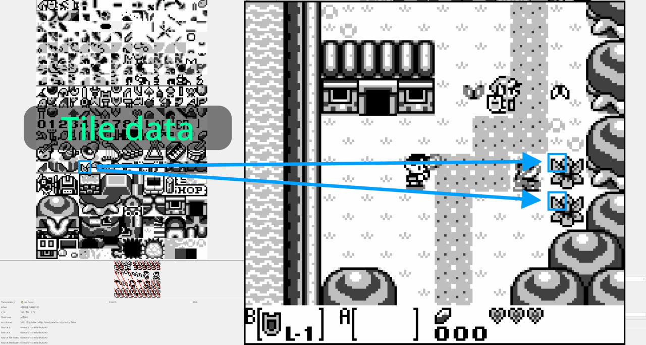
So, it makes perfect sense to use background tiles to create the image. Except for one problem: The tile map uses single bytes to address the tile data, which means that it can only address up to 256 tiles. Looking at the Game Boy’s resolution of 160x144 we need a total of 20 x 18 = 360 tiles. So, we need to employ a trick that is well-known among Game Boy developers.
There is a bit in the display status register that determines whether the tile map is based on the memory address 0x8000 or 0x9000. The tile data is stored there with a “color” depth of 2 bit, leading to 16 bytes per tile. So, if the tile map is based on 0x8000, the 256 addressable tiles with 16 bytes each just end at 0x9000. When the bit in the display status register is set, the tile map can address other tiles beyond 0x9000 and we can switch that bit with an interrupt3 just when we are half-way through drawing the image. The PPU draws the image line by line and in the upper half of the image we simply draw 0x8000-based tiles and in the lower half, the same addresses of the tile map change their meaning as we switch to 0x9000-based tiles. This way, we can use 384 different tiles, which is enough to draw an arbitrary image.
Wait, did I just write 384? Why not 2 x 256 = 512?
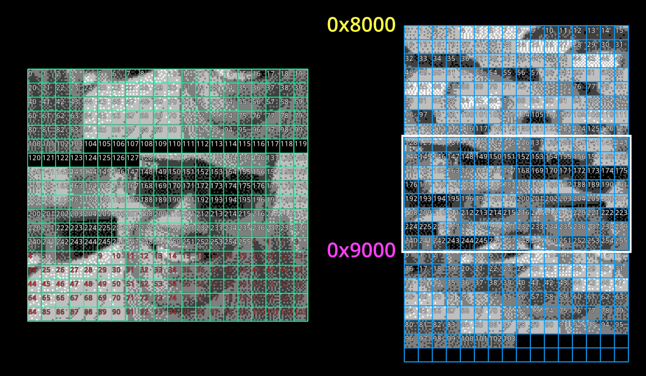
There is another change when setting the bit in the display status register that you have to be aware of: If it is not set, the tile map is interpreted as an unsigned integer. If it is set, it is interpreted as a signed one. So, while in one case we can address tiles in the range 0 to 255 relative to 0x8000, the other case addresses -128 to +127 relative to 0x9000. This leads to an overlap in the range 0x8800 to 0x9000 and the tiles here are the same. Therefore, we only have 384 tiles, which is still enough. In fact, the overlap is designed such that the binary representation of -1 as a signed integer to address the tile before 0x9000 is the same as the representation of 255 as an unsigned integer to address the same tile from 0x80004. What this means is that if we arrange the tile map such that we use tiles from the overlap area in the part on the screen where we want to switch between both addresses, our timing may even be a bit sloppy, because the same entry in the tile map would refer to the same tile in both systems anyways.
Now, that we know how to draw a full screen image, we can set up a fixed tile map and only need to transfer 384 tiles for each frame, right? How fast can we do this?
As each tile weighs in with 16 bytes and we need 360 per frame, we need a total of 5760 Byte per frame. Since the Game Boy does not have to do anything else in this demo, this would actually be fine if it really could transfer this data all the time. With my limited Assembly knowledge I need three lines of (repeating) code to transfer data from one memory address to another using the Game Boy’s instruction set:
1
2
3
ld a, [de]
ld [hli], a
inc de
The first line loads a byte from the source address into the register a, when the 16-bit register de already points to the source. The second line copies the byte from register a to the target memory address, already stored in the 16-bit register hl. This line also increments hl in the same instruction, so it points to the next address data needs to be copied to. Unfortunately, we need to increment the source address manually, so this is done with the third line. All three lines take up a total of 6 cycles. If we align our data properly and unroll any loop around this code, we can get it down to 5 cycles, because 16-bit registers on the Game Boy can be treated as separate 8-bit registers and we can just increment e instead of de, which saves one cycle. But we need to make sure to properly handle the overflow every 16 byte.
Luckily, the design of my WiFi cartridge makes this part a bit easier. The Game Boy has to read all the data from the same address: 0x7ffe. So we do not need the third line at all as de may perpetually point at the same source while the target address is automatically incremented. Therefore, we get down to four cycles per byte.
With a system clock of 1 MHz5, the Game Boy could therefore transfer the 5760 Byte for an image more than 43 times per seconds. If it was allowed to do so all the time. Unfortunately, the tile data has to go into VRAM and the PPU blocks access to VRAM while it is drawing the image. This makes writing data to VRAM really complicated.
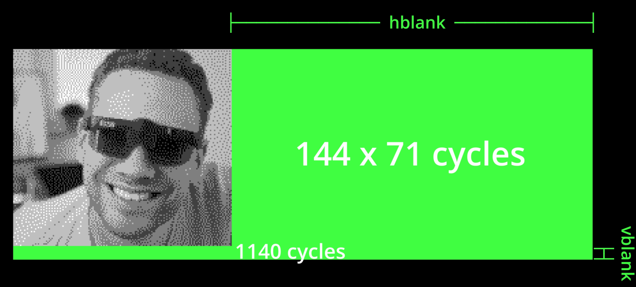
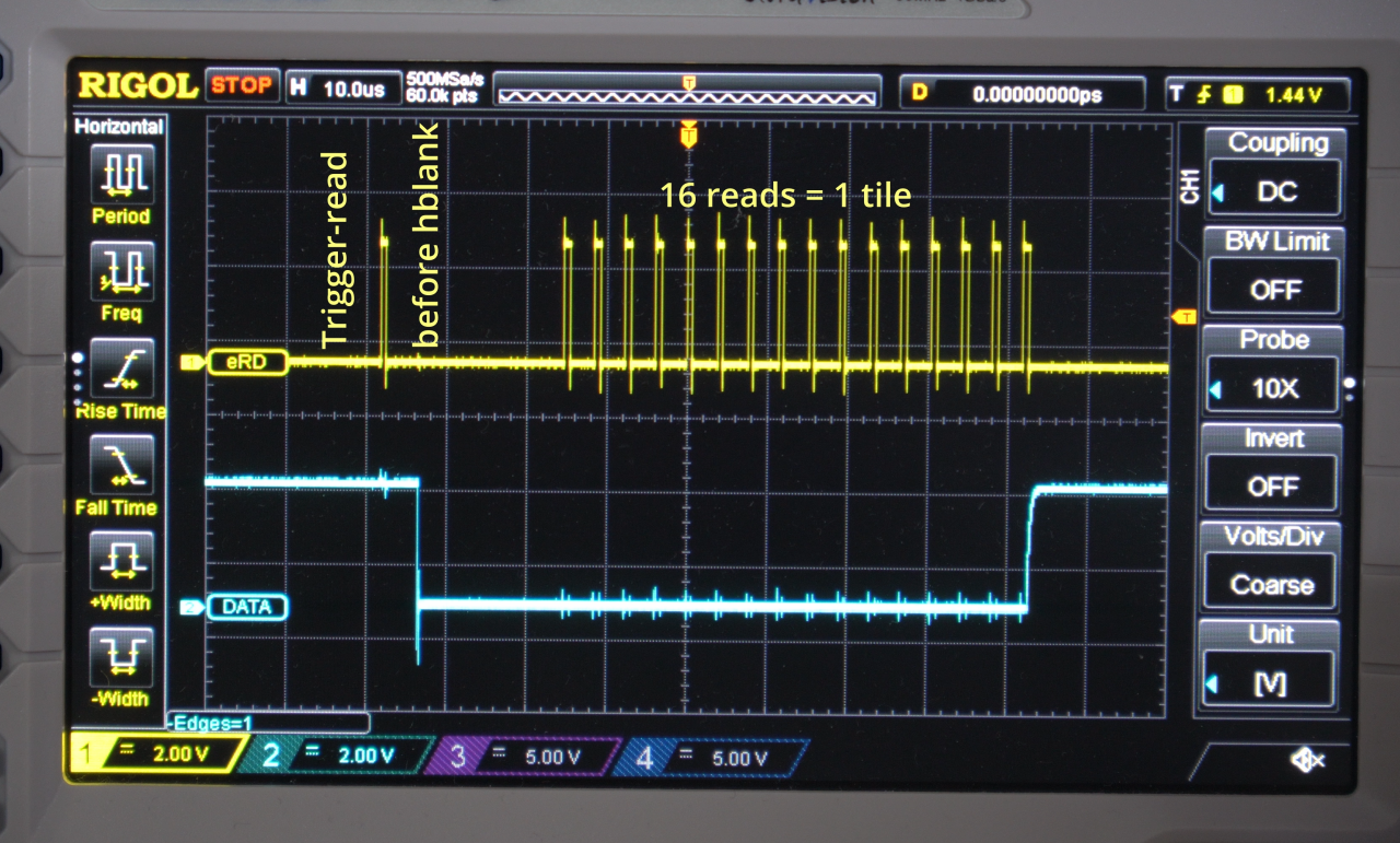
The PPU draws the image line by line from left to right and from top to bottom. On each line VRAM access is blocked while pixels are being drawn, followed by a period during which the PPU is working on OAM to prepare the tile data and a period called “hblank” during which memory access is unrestricted. The exact timing depends on the sprites and drawing functions that are in use, but for our simple case, these two periods last 68µs or 71 cycles6.
At the end of drawing the entire screen, we also get another free access phase that lasts about 1ms or 1140 cycles, called “vblank”. So, in total we get 11364 cycles and therefore 2841 Byte for each redraw. So, it is just not enough to get the image through in two refreshes - we need three of them7. As the Game Boy has a refresh rate of 60 Hz, this means that our video will run at 20 fps.
With three refreshes we then have some headroom to arrange the transfer, which is a good thing, because all those cycles are distributed across 144 hblank and one vblank periods, which makes timing and clever arrangement a bit tricky. With this headroom, however, we can do the following:
The 16 Byte of one tile just can be transferred in a single hblank period, so we split the 360 tiles into three blocks of 120 tiles and transfer them during hblank of the first 120 lines of each refresh. This still leaves the entire vblank block for other uses (we do not have any right now) and anything that does not require VRAM access can even be done during the remaining 22 lines (or even before each hblank, but that is even shorter than hblank itself).
We only use this little headroom for one additional feature: Sending one byte of data once an image has been completed (i.e. every three refreshes). This byte can be used for two things: On one hand, it can help synchronization with the ESP. It is a signal that the Game Boy expects the beginning of the next frame, so the ESP can skip to the next one if something went out of sync8. On the other hand, the data has a simple use: The Game Boy has eight buttons (A, B, Start, Select and four on the D-Pad), which can be perfectly encoded in one byte. This allows us to not only stream video to the Game Boy, but also to use the Game Boy to control games (or whatever we want to control).
To do all this, we need three pieces of software:
The Python script can be found in the new folder “python” on github. Actually, there are three scripts:
test-pattern.py generates a test pattern (sequence of solid colored tiles and a triangle tile) for development.video-stream.py takes a video file and streams it to the Game Boy (ignoring anything sent back from the Game Boy).game-stream.py does almost the same as video-stream, but uses the byte from the Game Boy to emulate keyboard inputs, i.e. to control games.All three scripts have only been tested on Linux, but should work with no or only little changes on other platforms and any required package can be installed via pip. You will need to go through the code to adapt things like IP address, video source or key assignments (in case of game-stream.py). Also, video-stream.py and game-stream.py require ffmpeg to read a video file or grab the screen, convert it to a four color palette and apply some dithering. Once this is all adapted to your needs, just run the script as soon as the Game Boy cartridge is ready.
The ESP code is similar to the one used in the older examples. Besides some changes in how the data is managed (we are transferring an exact number of bytes instead of null-terminated strings), there are two essential differences:
The Arduino code can be found alongside the old examples in “esp8266/stream” on github.
Now for the meat of the new demo. C and the gbdk-2020 is no longer sufficient here and I have rewritten the entire thing in Assembly. Since we do not need to do anything fancy, the basic structure of the code is extremely simple: We have three loops (actually counted in register B) with 120 reads from the ESP each. All loops except for the outermost are unrolled (using rgbasm’s repeat-feature) and all functions are done inplace (using rgbasm’s macros). There are not function calls, no stack pointer operations and barely any control structures. I also do not use any interrupts, but do the tile map address switch just after a fixed number of (unrolled) send loops. It is essentially only a long sequence of ld instructions to transfer the data.
An interesting aspect here is that the timing to transfer the tiles has to be so exact that reading the display status register to figure out if we are in hblank takes so many cycles (read operation, comparison, conditional jump) that it is not sufficient to properly align the following commands with hblank. I still use such structures, but at some points, you need to add some NOPs if you change anything that might mess with the alignment with hblank.
The Assembly code can also be found alongside the old examples in “gb/stream” on github and it will be built by the same Makefile. But as it is not written in C, you need RGBDS with rgbasm to compile it.
With this new demo, many other demos almost become obsolete. I can display anything and I can control anything that can be displayed on and controlled by my PC. Of course, the interface and image are almost unusable this way, so some dedicated implementations might still be interesting. And also, I did not touch audio here, which unfortunately was a big oversight by me when designing this cartridge.
I hope to see other projects picking up on this code example as the WiFi module can of course be replaced by plenty of memory to show full screen video on the Game Boy. Let me know if you do - I would love to see it!
As always, I highly recommend Michael Steil’s “Ultimate Game Boy Talk” to learn about the Game Boy’s architecture. ↩
Large compared to available sprites. Actually, the set is rather small compared to anything else. ↩
As you will see later, we do not use an interrupt in this demo, but in most cases you would want to use an interrupt for this. ↩
You should know about two’s complement and signed integers to understand this. ↩
Some sources including myself sometimes say the Game Boy runs at 4 MHz. While this may technically be correct and at least the PPU indeed does so, each operation of the CPU is bound to the memory bus running at 1 MHz. There is not a single instruction on the Game Boy that does not require a multiple of 4 cycles (in terms of 4 MHz), so it makes much more sense here to look at it as a 1 MHz CPU which requires at least one cycle (instead of four) for a NOP instruction. ↩
The difference comes from the fact, that the Game Boy does not run at exactly 1 MHz, but 1.049576 MHz (based on a power of two). ↩
In theory, we do not have to align the video frames with the screen refreshes. If you are thinking of vsync, we already collide with the redrawing multiple times and get some glitches this way. So, rearranging this better might allow for something like 2.5 refreshes leading to 30 fps and it might also reduce the collision glitches. ↩
In practice, the Python script (discussed later) lacks such a function, so things can still go out of sync there. ↩